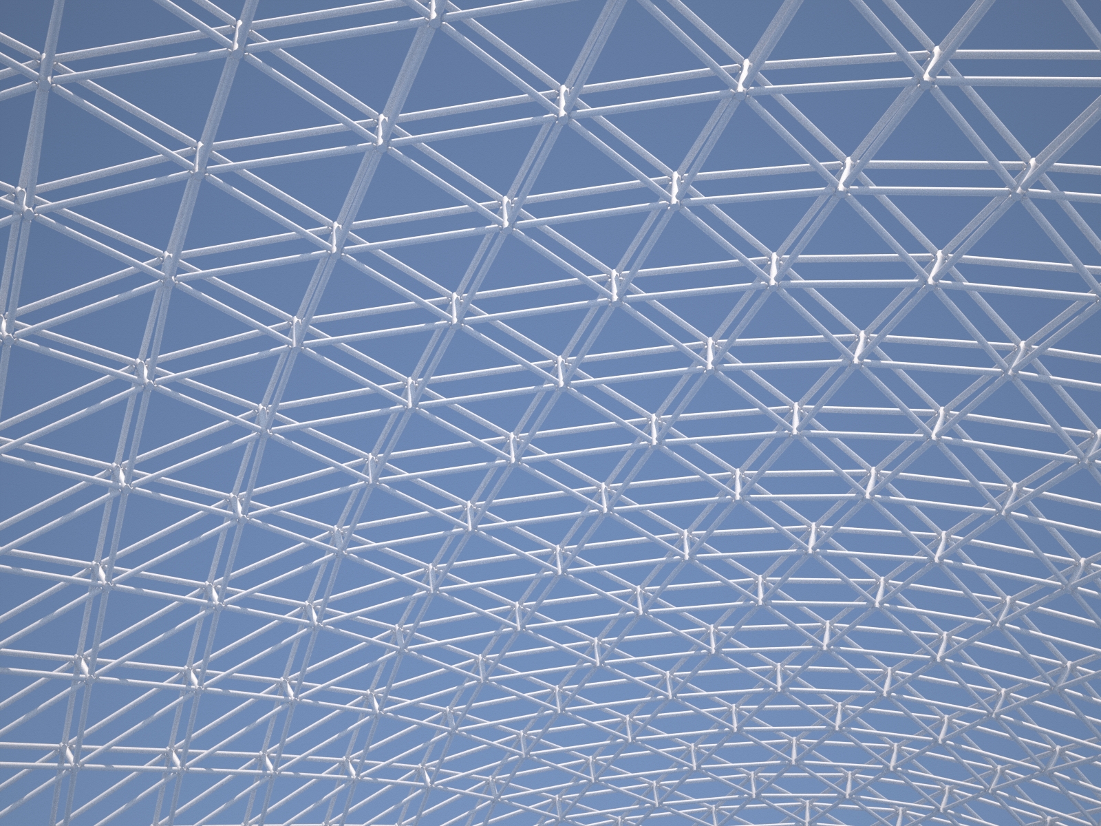
Building a parametric space frame structure
 This tutorial is trying to answer a question that was posted originally by Tom on the forum. So, I suggest you to read the original post here.
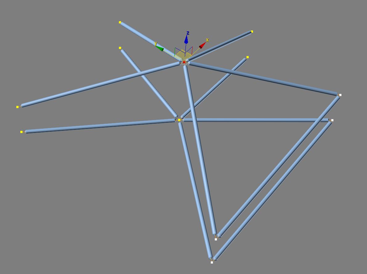
Our problem is to populate a given structure on the surfaces of spline base cage. The first answer comes in mind is to use Para 3d surface controller, However, the given object does not work with surface-controller. In first glance it looks like a smooth surface but it also presents singularities in different points.In Para 3d a surface by definition means a 2D plane that has been deformed into 3d space. The given object actually composed of multiple surfaces as it is shown in below image
- Step 1 – Breaking big problem to smaller problems:
Let’s start with breaking apart the object to multiple surfaces. I suggest use of NURBS surface. NURBS surfaces in 3ds MAX provides a normalized UV mapping that can be used to divide the surface uniformly. To build NURBS surface from the spline-cage I started with extracting the shapes that can form a loft surface. You can simply convert the Spline shapes to NURBS curve from right click menu. Notice that I left the segments with sharp corners. This is because the NUNRS CV curves cannot create sharp corners. Once the curves are extracted we can then create Loft surfaces from two or multiple curves. Switch off the display mesh of the NURBS object so that when you create the pattern you can see it clearly.
- Step 2 – Building an adaptive component.
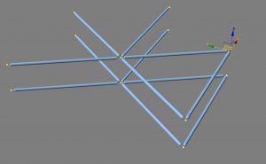
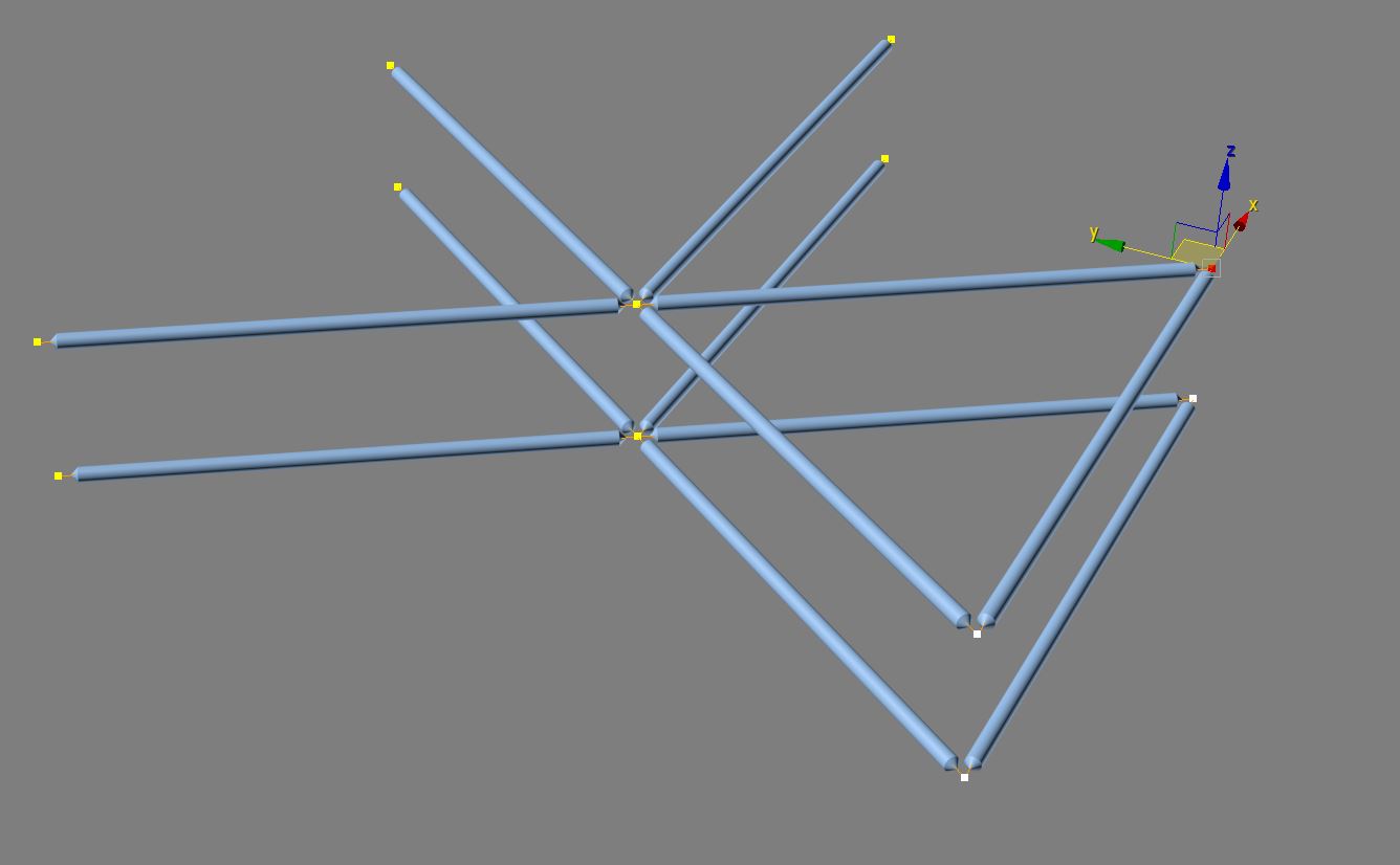
I use the term adaptive component because I’m mainly Revit user rather than MAX user! In Autodesk Revit a component that allows complex geometry to be built on a simple set of points defined by user is called Adaptive component. Here we create such an adaptive object by stacking up different modifiers on a simple object that includes verities in its base. This basic object can be an spline shape or editable mesh.In this case I chose Editable spline and because we only deal with straight segments (not curve segment) we must convert the segments to line segments and vertices to corner vertex.
- Step 3 – Converting shapes to meshes
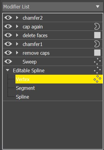
Here your MAX skills becomes essential. By adding sweep modifier on the base object you can get the basic from out. You can add as many as you need EditPoly modifier to the object, but make sure you rename them properly, otherwise the long list of modifier in Para 3d may become very confusing.Keep in mind if you need to alter a setting in EditPoly modifier you must set the modifier into animate mode.
- Step 4 – Testing the adaptive component.
Don’t move to the next step until you make sure that geometry can deform as you are expecting. The way I usually test my component is that I make a copy of the object and activate the “Show end result” in modifier stack, then I move the vertices of base object around. If the geometry updates as expected then we can proceed with next step. If not, figure out the problem!
- Step 5 – Building the sample pattern.
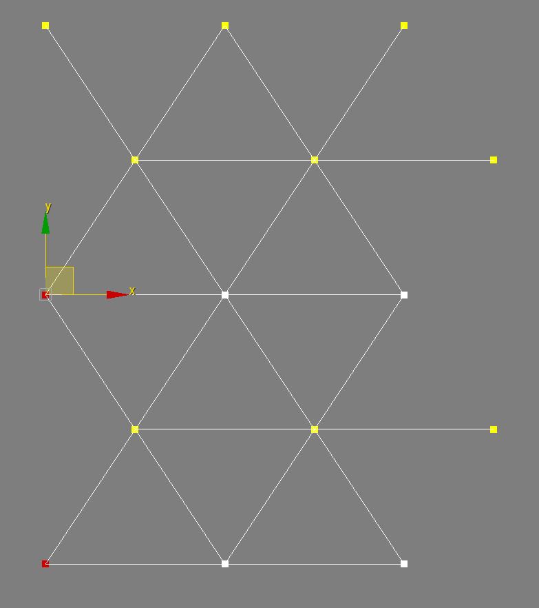 Since Para 3d surface controller will use the object bounding box to fit the objects on the surface divisions we will not get the desired result. The pattern which we are looking for is result of a specific layout of the given geometry. To build such a pattern we need to set a small example so that Para 3d can extract the required transformations from the sample pattern. In this case a 2X2 ( 4 items) will give enough information to Para 3d on how to build this pattern. Make sure you use instance cloning while making the sample pattern.Also for better snapping I turned off all the modifiers.
- Step 6 – Create Parametric Array
The NURBS surface which we built in first step can be used as 2D domain to divide the surface in two directions (U and V directions). So let’s build a 2d Array. don’t forget to allow access to the sub-object level. - Step 7 – Surface division
Use surface controller and sub-object controller to place the vertices of the spline shapes on the surface. Surface controller uses the offset values that are generated by Sub-object controller to push the vertices of the adaptive component to the corner of the surface divisions. The W offset controls the distance of the vertices from the surface along the normal vector. - Step 8 – Custom pattern
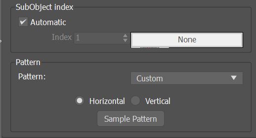
After updating the Para 3d in previous step , the objects cover the surface, however, the pattern which we are looking for is not obtained. To get the right pattern we need to inform Para 3d how to alter the divisions on the surface so that objects can fit in the correct location as we expect. Here you can use the sample pattern which you built in step 5. Choose custom pattern in Sub-object controller and then select the 4 instances of adaptive components. Click on the sample pattern button. There is no specific direction in choosing the pattern size and direction. In most cases default settings will work just fine. Some complex pattern may need a couple of try and errors.
- Step 9 – Adjusting parameters
Once the pattern is achieved, we can assign custom parameter controller to the parameters which may need further adjustments. - Step 10 – Linking the lower part and upper part
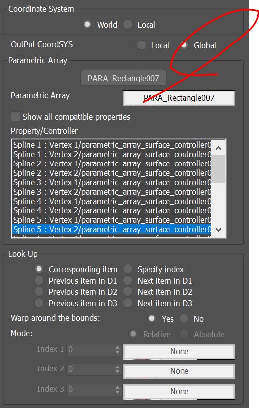
It’s time to connect the two layer of the structure. Create another 2D array of a spline shape with two segments. Look for the vertices that needs to be connected. Remember the index of the vertex and spline and find the same under the vertices list. Use Para-Link controller to connect corresponding vertices. Don’t forget to choose “Global” from Para-Link controller.
In below video you can watch all the steps in above and more.