Para EditPoly and Bitmap controller
In this article I’m trying to address a question by Ben Rabinson posted on Para 3d forum. For more information about the original post please see this link.
How does a Bitmap Controller work?
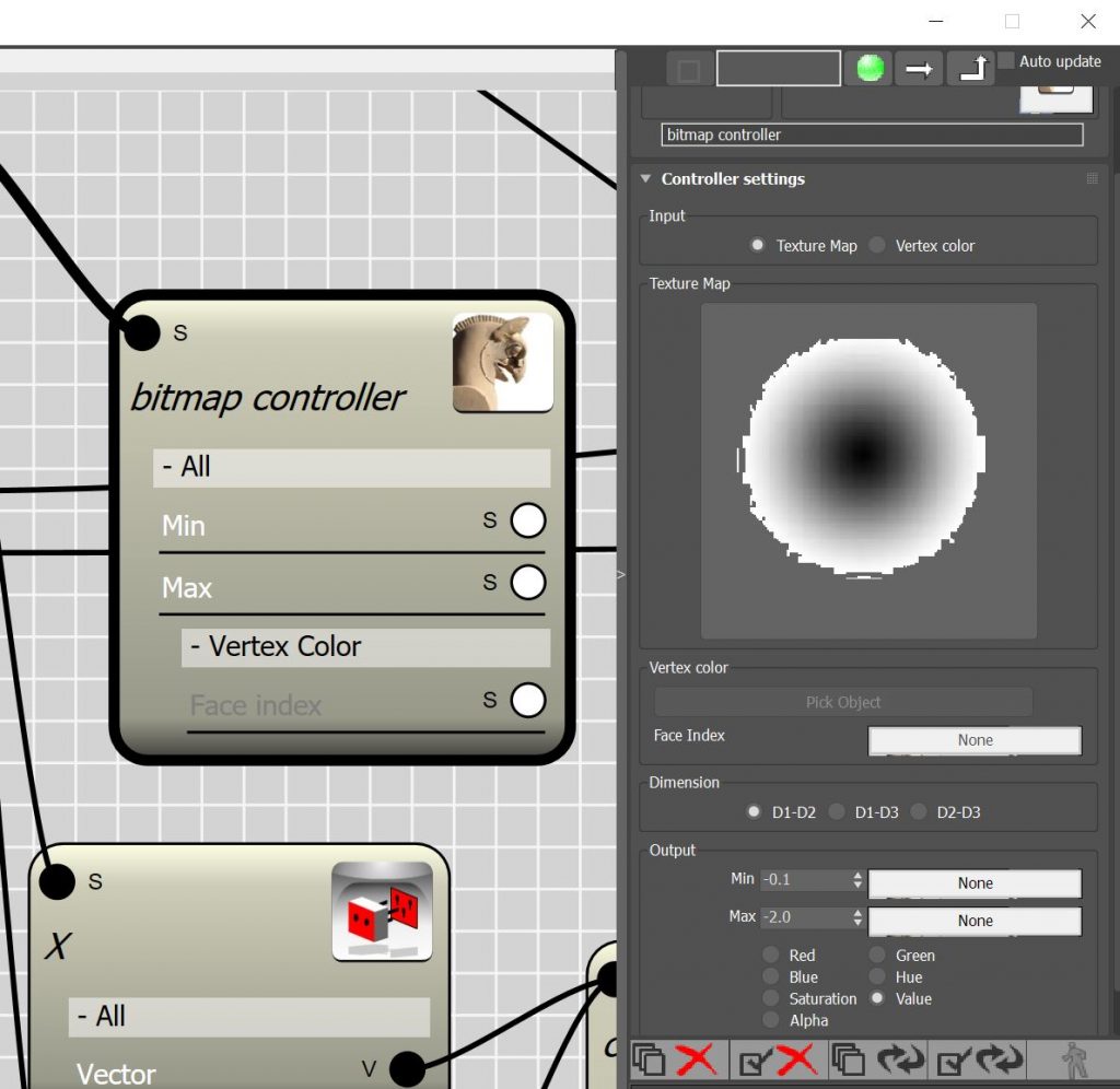
- Before we start , let me explain how Bitmap controller works. A Bitmap controller extract information from bitmaps and procedural maps. Maps are considered as 2D domain in which each point in the domain can be addressed by a 2D vector. Image below demonstrate bitmap that has been subdivided using an 18×18 domain.
![]()
- The Bitmap controller then create a table of the colors by finding the average color in each sample of the image.
- From this table we can now recall the value stored in each cell by having the vector position of that particular cell.
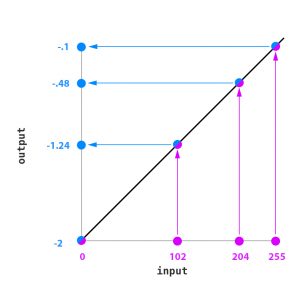
- Normally in each cell 7 values are stored that are corresponding to the Red,Green,Blue,Hue,Saturation,Value and Alpha of the sample. Each of these values can vary between o to 255. Once the value is retrieved it will be remapped to the out put range. for example if you choose -.1 and -2 for the Min and Max range , the output will be adjusted to the target range using a linear mapping technique.
Create 2D domain for Bitmap Controller
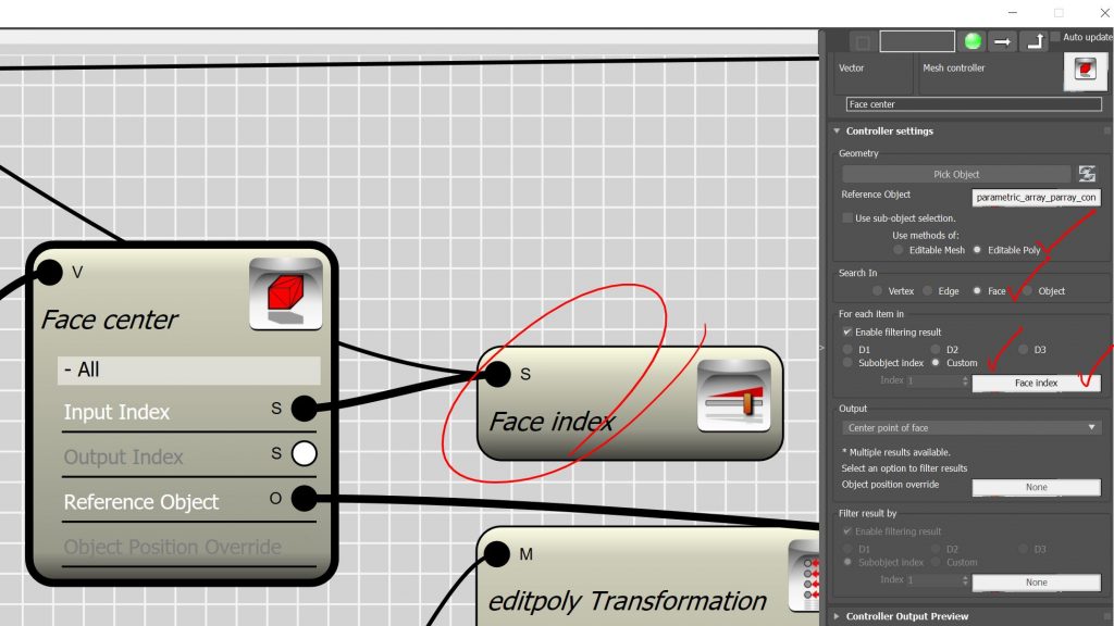
So now we know that Bitmap controller works on 2D domain, but how do we provide a 2D domain ? If the controller was assigned to a parametric array with members in both dimension we could easily choose D1-D2 in dimension settings and map the array members to the bitmap. But in Edit-Poly node we have only one node as input. Even thinking about the faces of edit-poly , they are stored in 1D fashion and access to each face is provided by an integer number which we call it “face index”. The only way to create a 2d domain from the faces of an edit-poly ( in this case is a plane object) is to find the center point of the face in respect to the local coordinate system of the node. Here we have to parameter to build , first parameter is the center point of the face , well that’s the easy one ! we can use Mesh controller and the Face index for find the center point of the face. The face index can be extracted from Sub-object index channel of the Edit-Poly node.
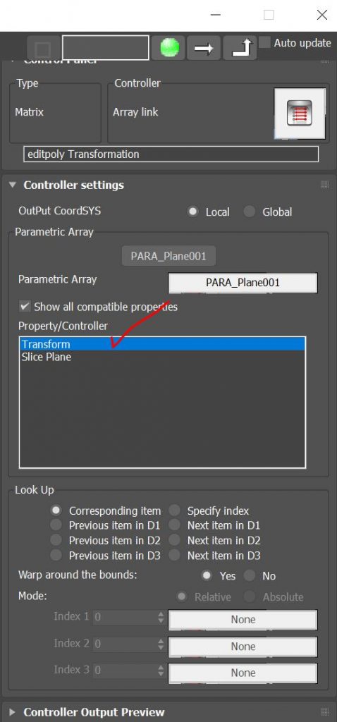
- The second parameter is the local coordinate system of the given edit-poly object. You probably say that’s even easier, I can use Para link controller to retrieve the transform property of the object.
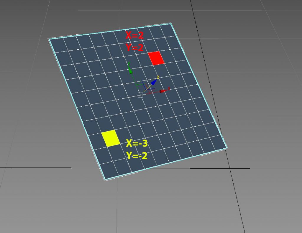
- well it’s only the first step. because when you retrieve the transform property , you can actually use it as local coordinate system, however, the transformation is given by considering the location of the pivot point in the object. In this case the origin of the local coordinate system will be in the middle and when we try to calculate the coordinates of the face center in respect to this system we will end up with negative numbers for X and Y coordinates in 3 quarter of the plane.(See Fig. A)
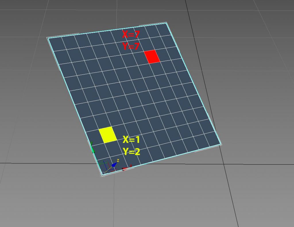
(Fig. A) (Fig. B)
- The negative numbers cannot work with Bitmap controller. The solution is either to push the origin of the coordinate system to the left-bottom corner of the plane or remap the numbers from the {-L/2,+L/2} to {0,L}.(See Fig. B)
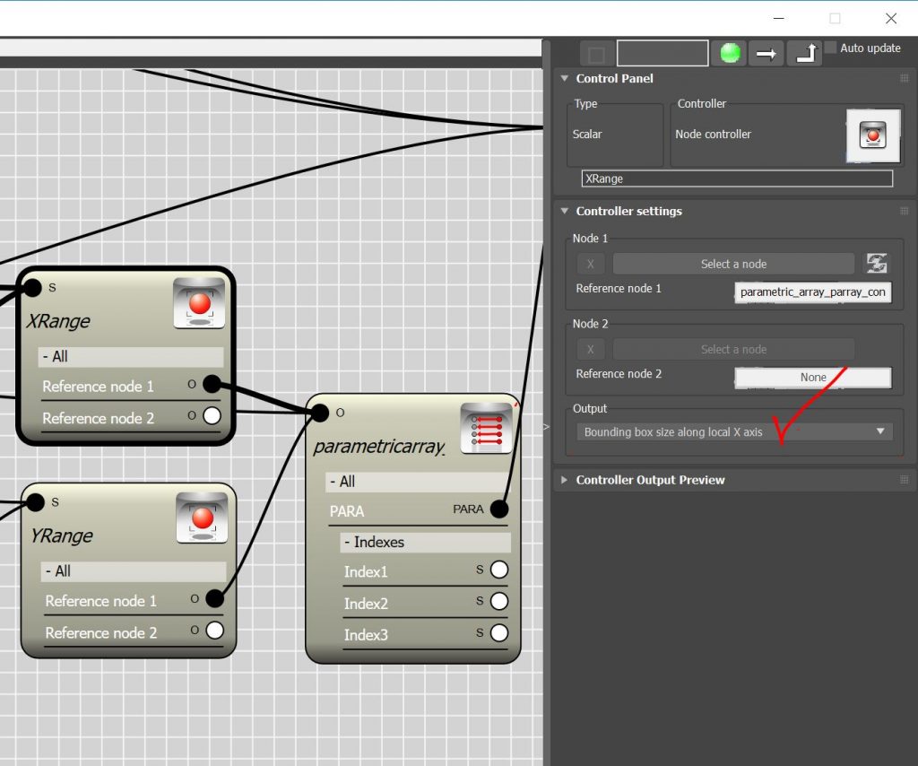
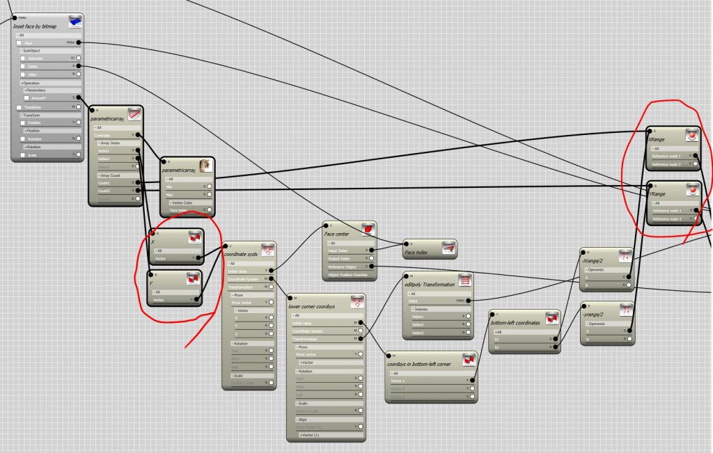
- In this video I took the first approach. To push the origin of the local coordinate system we need to find the size of the plane in respect to its local coordinate system. Node controller is where you can find this information. The size of object bounding box along the local X and Y is the number we are looking for. I created to Node controller which can extract these information from the edit-poly object and rename them to X-range and Y-range.
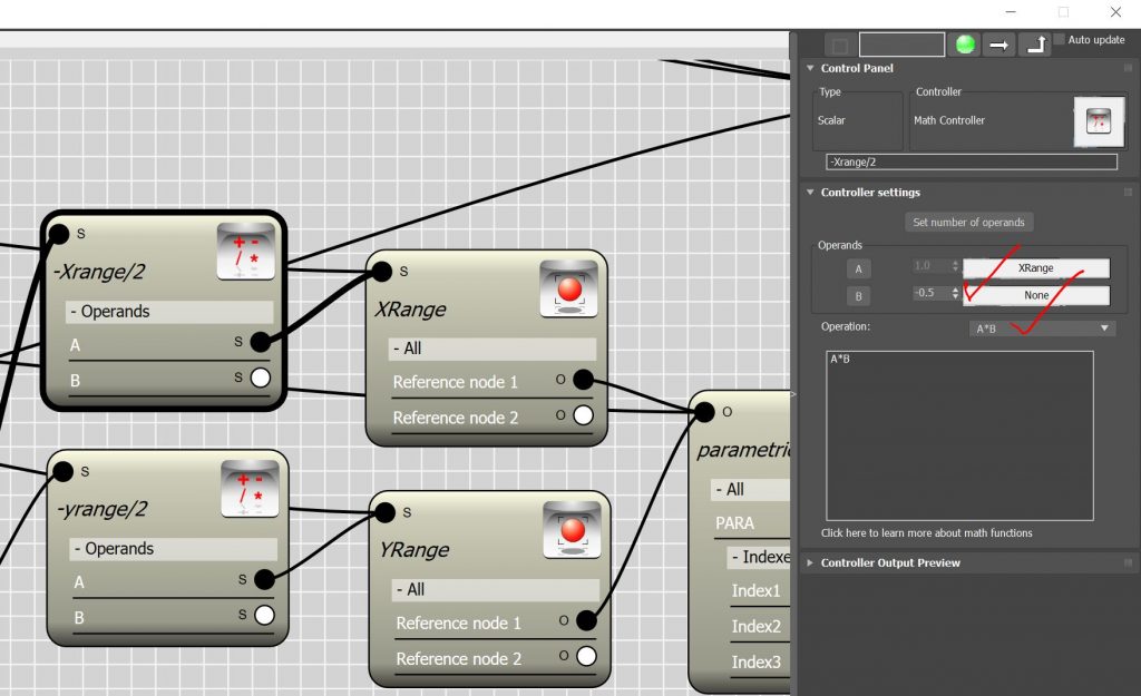
- The origin point must be moved by half of the size of the plane. So I used the Math controller to multiply the outcome of the Node controllers by -.5 . Now we have the X and Y coordinate of a point which represent the coordinate of the left-bottom corner of the plane in it’s local coordinate system.
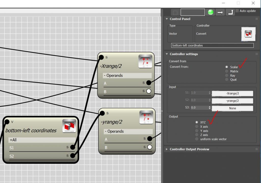
- To use these scalar values as coordinate system we need to convert them to transform matrix value. First we must create a vector using the two scalar value.
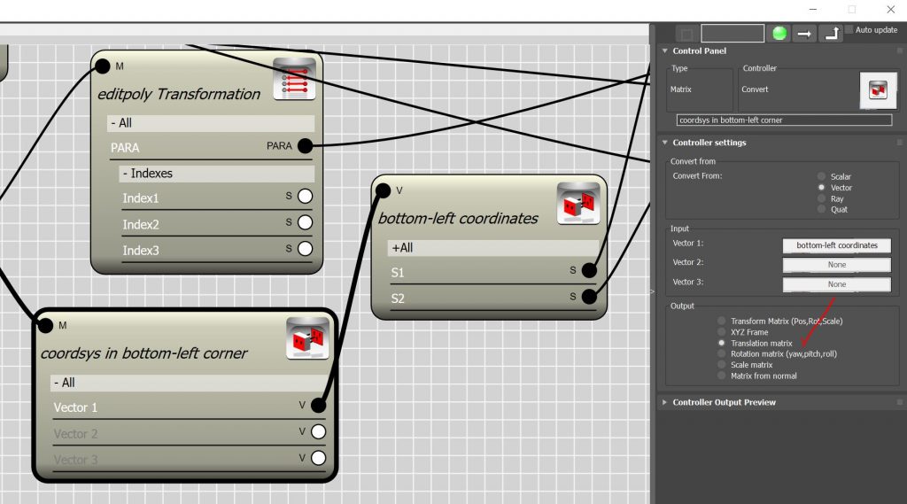
- Then we create a transitional matrix to convert the vector to a Transformation.
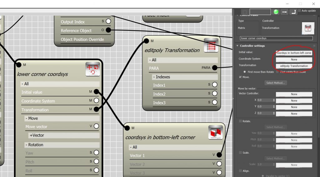
- Last step is to transform the transitional matrix by the plane transformation so that we can use it as coordinate system in the next transform controller.
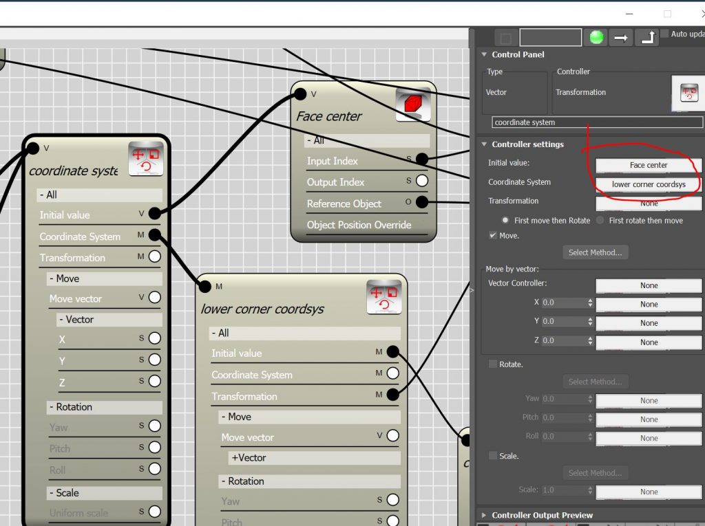
- When you add a transformation to “coordinate system” channel of a transformation controller the output represent the local coordinates of the initial value in the given coordinate system. So let’s assign the Face center which is found in global coordinate system to initial value and our transformation for left-bottom corner to coordinate system channel to find the center of the face in the newly created coordinate system. The output will be a vector with positive components varies between zero and X-range or Y-range respectively.
Inform Bitmap controller about your custom made 2D domain
- Now we have computed the X and Y coordinates of the face center , how do we use this in Bitmap controller, there are no option to plug the X and Y to the controller. Bitmap controller works based on the indexes and counts of the parametric array. To inform the Bitmap controller about the X and Y value we need to override the indexes and counts. This can be done by using the Bitmap controller under a Variable override controller.
- The Count1 and Count2 values are referring the to domain size in the first and second dimension, so we override them by X-range and Y-range from our Node controllers( remember that they are representing the size of the plane in respect to local X and Y axis) . The Index1 and Index2 value are referring to the location of member (in this case a Face) in respect to the given domain, so we override them by the X and Y which we calculated from above.
Everything is ready to go! give it a try. don’t forget to hide the original edit-poly to see the result. you can also add another edit-poly to remove the resulted faces.
